Software Design
Our robot’s original plan was to use its long arm to reach the middle three bins. In this way, it would be able to avoid turning entirely once it oriented correctly and found the tape. Instead, it could use pure tape sensing to travel up and down the tape line. Also, since the arm was very long (30 inches from the chip-holding hopper to the back of the robot when fully extended) it would need to travel a much shorter distance between the bins and the Super PAC, cutting down on travel time and increasing token drop quantity.
Our other important innovation was to attach a beacon sensor to the arm’s post so that it would point in the same direction as the arm. In this way, we hoped to turn until we faced a beacon, then drop tokens, guaranteeing that even if the robot was slightly off center, it would correctly drop tokens into a bin.
Our original state diagram is shown below:

Our plan in the original code was to spin until the robot had seen both the PAC and the beacon and record the times of each. By defining a “threshold time” of roughly the time taken to spin 180 degrees, and remembering whether it had seen the beacon or PAC first, it could determine which side of the field it was on, and therefore whether it was facing the right way or not. (If it took a long time to see the beacons, then the PAC, it knew it was on the left side of the field. If this was the case, it needed to continue spinning so that when it split the angle, as described below, it would face forward.)
Then, it would spin backwards half the time between the two – hopefully allowing it to split the angle roughly equally between the nearest beacon and the PAC – and then drive forward. We believed that this would give it a good chance of hitting the center tape line, rather than the line that went along the front of the field. Later, we changed the angle to two-thirds of the way towards the PAC to be more secure. Once its center tape sensor was on the tape, it would enter “initial tape-orient” state, where it would spin around – in a direction determined by which side of the field it was on, which it learned earlier – until its center sensor was on tape, at which point it would stop and drive forward. Once its left and right sensors were both on tape, it would know it was on the T, at which point it would stop and its servo arm would spin outwards. Once it encountered a beacon at approximately 135 degrees (where the center-left beacon should be) it would drop its tokens.
From this point, it would enter “the main loop”. It would reverse until its back bumper hit, wait for tokens to be loaded and the fully-loaded switch to be hit. Then it would move forward until it hit the T, scan for a beacon (ignoring anything before a certain threshold to avoid seeing the far beacon), and then drop when it saw a beacon. Then it would reverse, repeating the loop.
However, we realized that this plan was technically a violation of the rules – because our arm was so long, when the robot was parked at the T, the arm actually extended over the other side of the bin. (It was also a problem for us – we didn’t want to drop into the other side!) We would need to reverse once the arm reached a certain angle. Rather than going to the trouble, we developed a new state diagram:
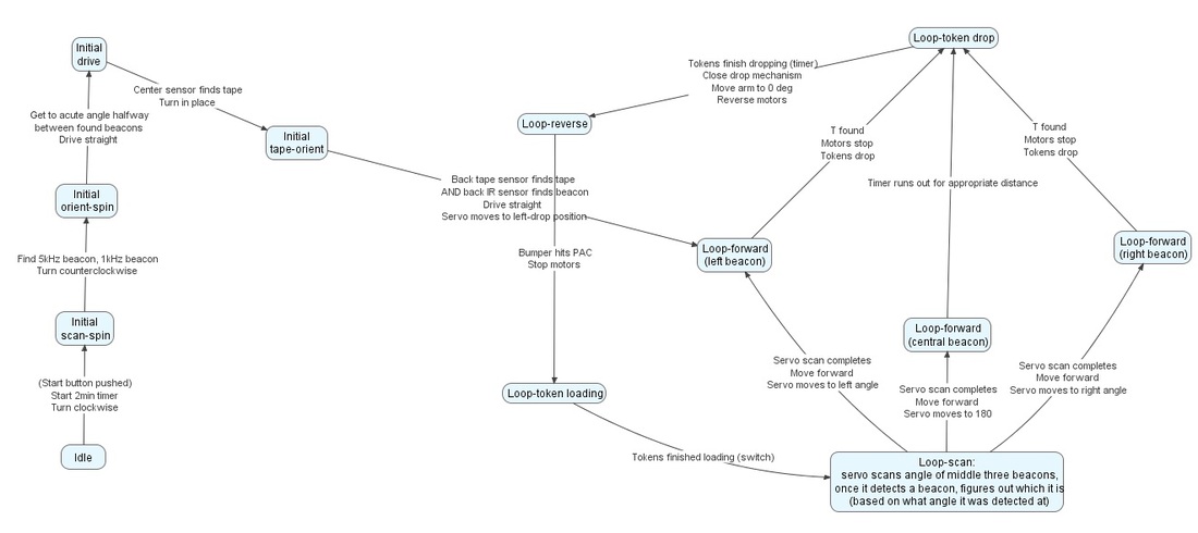
This new method involved using the arm to scan for beacons right after tokens were being loaded at the Super PAC. Once it found a beacon within one of the three middle “bins” (angles experimentally determined), it would know that a reachable beacon was on and which one it was, and could begin moving. If it was aiming for the left or right beacon, it would find the T; if it was the center one, the arm was actually long enough that it would only need to cover about 10 inches of ground! We decided that rather than going to the T and reversing, we would simply program in a timer, after which it would stop and unload its tokens.
--
For tape following, we had the following system: Since there were four tape sensors, one in the center and three very closely spaced at the front (hereafter referred to as “left”, “front” for the middle one, and “right”), once on tape it could sense when either the left or right sensors found tape. If this happened, we knew it was veering off the straight line, and would give it a “burst” of correction until the side sensor lost signal. We put the tape sensors into the analog input pins on the Arduino, allowing us to control the reflectance thresholds at which the sensors sensed tape. This allowed us to use software to bypass the additional complexity of building filters to distinguish high from low, and allowed us greater flexibility in changing those thresholds as appropriate (as an example, one of our tape sensors was different from the others, and ended up requiring a different threshold).
--
Having only two beacon sensors allowed us to use the interrupt pins (2 and 3) on the Arduino Uno to determine the frequency of incoming signals, rather than relying on the active narrow-pass filters which we were considering using. We had an interrupt trigger to record the time at which each rising change was received, then used the Arduino library “RunningAverage” to keep an average of the time between the last 20 signals. By using threshold values around 850 Hz and 5 kHz, we were able to distinguish between the beacon and PAC signals.
Looking back, it is possible that the interrupts caused us problems later on. Unreliable beacon sensing was a problem in our robot until the end – it would sometimes sense beacons where there were only walls, or fail to sense beacons entirely. Also, the servos on the robot would “twitch” whenever the robot sensed beacons, a sign that something about the sensing was causing problems with the rest of the machine. We suspected that it had something to do with using interrupts.
--
When we began testing code on the complete robot which involved more than testing subsystems, we ran into trouble with tape following. The momentum of the robot would consistently cause it to overshoot the intended target, whether that was stopping on the tape or stopping when orienting straight forward. To correct this problem, we added “hard stop” code – whenever the robot reached a point where it needed to change direction, it would first run the motors at full speed in the reverse direction for some amount of time (controlled by a timer). The necessary length of time had to be experimentally determined. For the point at which it was first driving onto tape, we also had the robot slow down once the front sensor crossed tape, so that the hard stop did not have to deal with as much momentum. The correct timing turned out to be about 60 microseconds for stopping on tape, and about 50 microseconds for turning onto tape.
While attempting to course-correct once orientation was achieved, we realized that because our tape sensors were very close together, when the robot was correctly oriented, the left and right sensors would be partially on tape, and read a reflectance intermediate between the on-tape and off-tape states. Because we were using analog inputs rather than digital ones for the tape sensors, we were able to take advantage of this additional information, resulting in a code which turned the motors at different speeds proportional to the difference between the reflectance of the two sides, attempting to balance them.
We used a similar strategy for our initial orientation onto the tape. The robot would first perform a “coarse turn”, a simple turn at fairly high speed. When one of the side sensors detected tape, however, it would move into a “fine turn” state, where it tried to balance the left and right sensors’ reflectance while keeping the front sensor on tape. This seemed to be less successful than a simple hard stop followed by tape following using the new method, seemingly because while it was performing the “fine turn”, it would rotate so far off tape that all sensors were off tape, which invalidated the fine turn code.
While our tape-following method was very accurate when moving forward, the robot still had considerable trouble staying on tape moving backward. Since the tape sensors are located at the front of the robot, small drifts were quickly sensed when moving forward, but when moving backward, the side sensors sensing tape came too late – the robot had already moved quite far off the tape. To attempt to counteract this problem, we attached two additional tape sensors to the back of the robot. However, possibly due to issues with orientation or spacing of the tape sensors, we could never quite get them to work properly.
--
Because of our continuing issues with proper tape following, with our checkoff deadline approaching, we scrapped large portions of the code (keeping only the modules dealing with spinning the motors, sensing beacons and bumper hits, and controlling the servos) and developed an alternative, streamlined code. In this configuration, the arm no longer moved, and the robot simply moved between two “meta-states” – moving towards a beacon, and moving towards a PAC. The state diagram is shown below:
--
For tape following, we had the following system: Since there were four tape sensors, one in the center and three very closely spaced at the front (hereafter referred to as “left”, “front” for the middle one, and “right”), once on tape it could sense when either the left or right sensors found tape. If this happened, we knew it was veering off the straight line, and would give it a “burst” of correction until the side sensor lost signal. We put the tape sensors into the analog input pins on the Arduino, allowing us to control the reflectance thresholds at which the sensors sensed tape. This allowed us to use software to bypass the additional complexity of building filters to distinguish high from low, and allowed us greater flexibility in changing those thresholds as appropriate (as an example, one of our tape sensors was different from the others, and ended up requiring a different threshold).
--
Having only two beacon sensors allowed us to use the interrupt pins (2 and 3) on the Arduino Uno to determine the frequency of incoming signals, rather than relying on the active narrow-pass filters which we were considering using. We had an interrupt trigger to record the time at which each rising change was received, then used the Arduino library “RunningAverage” to keep an average of the time between the last 20 signals. By using threshold values around 850 Hz and 5 kHz, we were able to distinguish between the beacon and PAC signals.
Looking back, it is possible that the interrupts caused us problems later on. Unreliable beacon sensing was a problem in our robot until the end – it would sometimes sense beacons where there were only walls, or fail to sense beacons entirely. Also, the servos on the robot would “twitch” whenever the robot sensed beacons, a sign that something about the sensing was causing problems with the rest of the machine. We suspected that it had something to do with using interrupts.
--
When we began testing code on the complete robot which involved more than testing subsystems, we ran into trouble with tape following. The momentum of the robot would consistently cause it to overshoot the intended target, whether that was stopping on the tape or stopping when orienting straight forward. To correct this problem, we added “hard stop” code – whenever the robot reached a point where it needed to change direction, it would first run the motors at full speed in the reverse direction for some amount of time (controlled by a timer). The necessary length of time had to be experimentally determined. For the point at which it was first driving onto tape, we also had the robot slow down once the front sensor crossed tape, so that the hard stop did not have to deal with as much momentum. The correct timing turned out to be about 60 microseconds for stopping on tape, and about 50 microseconds for turning onto tape.
While attempting to course-correct once orientation was achieved, we realized that because our tape sensors were very close together, when the robot was correctly oriented, the left and right sensors would be partially on tape, and read a reflectance intermediate between the on-tape and off-tape states. Because we were using analog inputs rather than digital ones for the tape sensors, we were able to take advantage of this additional information, resulting in a code which turned the motors at different speeds proportional to the difference between the reflectance of the two sides, attempting to balance them.
We used a similar strategy for our initial orientation onto the tape. The robot would first perform a “coarse turn”, a simple turn at fairly high speed. When one of the side sensors detected tape, however, it would move into a “fine turn” state, where it tried to balance the left and right sensors’ reflectance while keeping the front sensor on tape. This seemed to be less successful than a simple hard stop followed by tape following using the new method, seemingly because while it was performing the “fine turn”, it would rotate so far off tape that all sensors were off tape, which invalidated the fine turn code.
While our tape-following method was very accurate when moving forward, the robot still had considerable trouble staying on tape moving backward. Since the tape sensors are located at the front of the robot, small drifts were quickly sensed when moving forward, but when moving backward, the side sensors sensing tape came too late – the robot had already moved quite far off the tape. To attempt to counteract this problem, we attached two additional tape sensors to the back of the robot. However, possibly due to issues with orientation or spacing of the tape sensors, we could never quite get them to work properly.
--
Because of our continuing issues with proper tape following, with our checkoff deadline approaching, we scrapped large portions of the code (keeping only the modules dealing with spinning the motors, sensing beacons and bumper hits, and controlling the servos) and developed an alternative, streamlined code. In this configuration, the arm no longer moved, and the robot simply moved between two “meta-states” – moving towards a beacon, and moving towards a PAC. The state diagram is shown below:
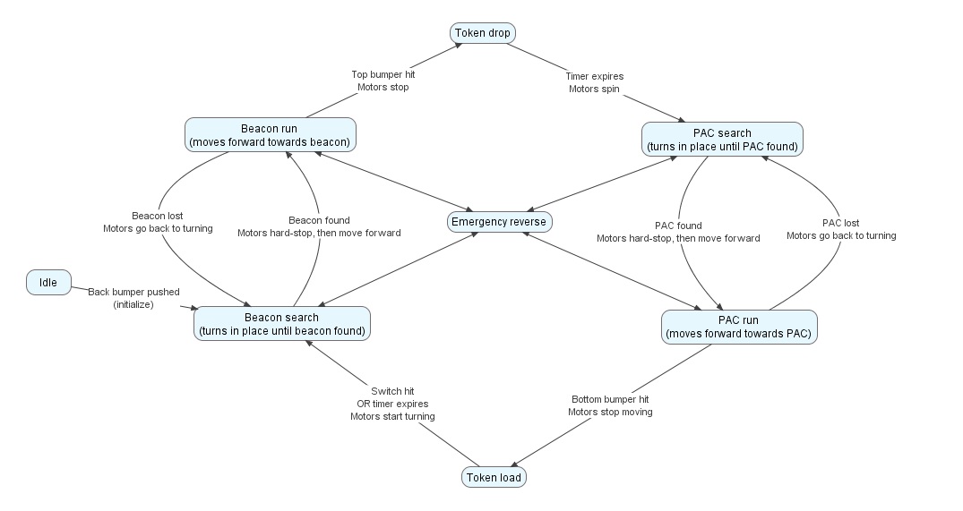
This very basic code, which didn’t incorporate the “hard stop” developed earlier, managed to “beat the brick” but had the unfortunate habit of losing the beacon because its angular momentum carried it off balance. Despite our best attempts at creating a hybrid code, in which the robot would swing out its arm at the beginning of the match and act as a sort of extremely long robot, we eventually reverted to the simplest version of the code, only adding “hard stop” code and an emergency escape mode, where it would reverse for a second and a half after ten seconds of being stuck in any given meta-state, hopefully extracting itself from any sticky situations such as being stuck between two bins.
