Mechanical Design
StrategyOne of our main strategies for the Super Pac competition is to minimize the time between scoring and reloading. One design that we came up with to accomplish this is a deployable mechanical arm that would extend the reach of our scoring mechanism. The arm would be rotated with a servo so that it can be extended to minimize the amount of driving required by the robot when trying to score. The arm can also be stowed away when reloading and at the start, so that it can fit in the 11"x11"x12" prism. This design allows the art to also reach multiple tumblers but will only require the robot to drive in a straight line. Our other strategy is to only concentrate on the middle three tumblers and to always dump the whole payload into a single tumbler each time it is trying to score. We feel that this would be better so that we do not spread our efforts too thin. We would be able to dominate 3 tumblers against most other robots who try to go for all 5 tumblers, especially given our shorter reloading-scoring time. This strategy also minimizes software complexity because we do not have to turn or find our way to the outermost bins.
|
ChassisChallengeThe robot needs to be durable enough to be able to withstand all the testing during the project and be shaped to maximize the reach of the arm. The robot also needs to be able to be easily taken apart so that we can easily access different subsystems. Finally, the robot must be allow for the mounting of all subsystems in an organized manner.
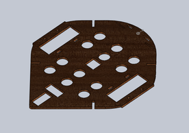
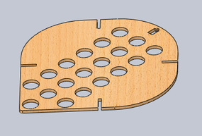
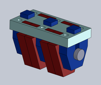
SolutionOur solution used a system in which we had three tiers to better organize our robot. The bottom tier was mainly used to mount the sensors and mechanical hardware (Motors, etc.). This tier was made from a hardier 1/4 inch masonite. This provided a convenient base to mount components. Four Pillars were attached to the bottom tier to allow for the addition of the middle and top tiers. Since less structural components were mounted on the other two tiers, 1/8 inch masonite was used instead. Electronics were mounted on the middle tier. Holes were placed in the tiers to allow wiring to go in between tiers. Tiers were easily removed as only the bottom tier was attached to the pillars with glue. This allowed for easier access when repairs or modifications were needed. The chassis was also designed so that the arm could be mounted at the very tip of the robot so that the arm could be the maximum length of the hypotenuse of the 11X11 in square. The additional tiers also provided stability to the arm.
Design ChoicesMasonite: Masonite was a good choice of material. The thicknesses that we chose for each tier was appropriate for the need it fulfilled. Masonite was also a good, cheap material that we could laser cut. This allowed us to make more prototypes easily.
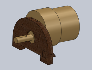
Shape: The shape of the chassis allowed us to maximize the arm length. The rounded shape on the back prevented us from being stuck in certain situations. The spear shape on the front would guide us to the tape if we hit the superpac in initialization. Tiers: The tier system proved to be invaluable as it allowed us to minimize the amount of clutter. The robot was also taken apart on several occasions, so this feature proved most useful. ArmChallengeThe robot needs to have a swiveling arm that will allow it to deposit tokens into the three center bins. It needs to have a range of at lease 225 degrees and must not have significant deflection when the maximum load was applied.
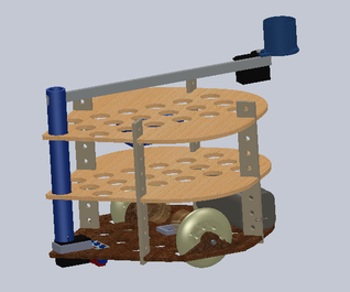
SolutionA vertical shaft, made from PVC, was attached to a 360 degree servo through an adapter. Notches were first milled on the shaft. Next an adapter piece was cut out, with this adapter piece press fitting into the servo horn and the shaft press fitting into the adapter. On the top of the shaft, two more notches were cut out. This allowed for the arm to be fit in. The arm was made with honeycomb aluminum to reduce weight but keep strength.
Design ChoicesHoneycomb Aluminum: The honeycomb aluminum that we used for the arm allowed us to have maximum extension with minimal deflection. The low weight of the structure was also helpful.
360 Degree Servo: The servo allowed us to reliably go back to a particular position each time. It also had minimal complexity, as a stepper motor design would have required substantially more hardware and software. HopperChallengeThe robot needed to be able to easily dispense 12 tokens at a time. The hopper would be able to indicate to the robot when it no longer had the 12 tokens. Also, the hopper needed to be as compact as possible so that it can be mounted further out on the arm.
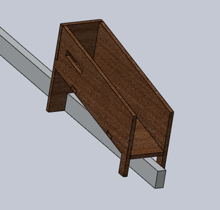
SolutionThe hopper was made to load 2 magazines of 6 tokens onto a 20 degree ramp. We utilized a servo and an extended servo horn to act as a gate for the tokens. The servo could rotate 90 degrees to let the tokens roll out. A leaf switch was also utilized to indicate whether or not the 12 chips had been dumped. The switch was inserted in slot in the hopper so that it would be pressed down only when the second set of 6 chips were loaded in. This hopper was chosen over the original tube hopper because it was more compact and could be placed further out. This would give us greater reach when we extended. It was also better that the tokens rolled since they would have some horizontal momentum.
Design ChoicesRolling Dispense: This design allowed the tokens to go further and also reduced the amount of stress experienced by the servo. This design was also more compact and gave us greater effective range.
Drive SystemChallengeThe robot needs a way to mount motors and wheels so that can allow the robot to move in a stable and consistent manner.
SolutionThe motors were mounted to a piece of masonite that was press fit into the bottom tier. There are holes in the masonite that allow the motor to be screwed in. A spacer is attached to the shaft of the motor so that the wheels would be at a consistent distance relative to the center of the robot. Acryllic hubs were glued to the wheel and then press fit onto the shaft.
Design ChoicesPress fit wheels: By having the hubs press fit into the shaft. The wheels were very stable and did not require support from the outside. Although it became more difficult to remove, the wheels performed much better.
Sensor MountsChallengeMount sensors so that they would be stable and be at appropriate positions.
SolutionSensors all had their own particular housing made from masonite. The sensors would be secured using glue or screws and the housing would be then press fit into place. One exception is the arm IR sensor which is embedded into the servo horn. It is lined up with the arm so that it sees where it will dump tokens into.
|