Circuit Design
IR Beacon Sensors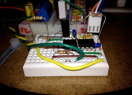
We chose to include two sets of beacon sensors on our robot using IR sensitive phototransistors. We designed two identical circuits to filter and condition the incoming signal. The circuit consisted of a buffer circuit, a passive high pass filter, non-inverting gain circuit, and a comparator circuit operating in the listed order using the LMC6484 op amp.
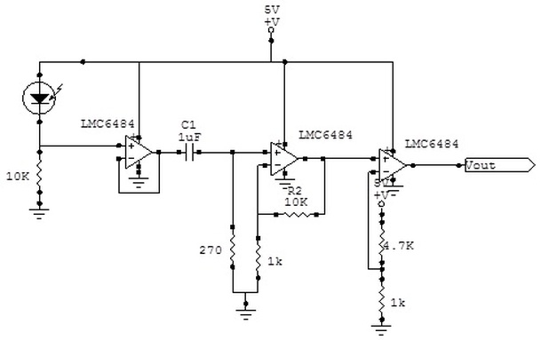
First, we chose to include the initial buffer to ensure an adequate power source for perpetuating the signal through the circuit.
Second, our high pass filter was a simple RC high pass filter designed with a corner frequency of approximately 600Hz. In reality our circuit operated with an ideal corner frequency of about 589Hz. We chose to use a filter value in this range in order to put a full decade of filtering between our nearest identified noise source: fluorescent lights. We felt the 60Hz lights could distort our readings so we chose to filter it out. We did not need to use any low pass or notch filtering because our frequency measurement would all be done with software. Next, we built a gain circuit to sufficiently boost our incoming, now cleaned up, signal. We had some difficulty identifying how much gain we wanted to include in the circuit. This stemmed from two sources: First, when building the high pass filter, we mistook a 102K capacitor to have a much larger value. As a result, we ended up with a high pass filter with a corner frequency several orders of magnitude higher than expected. As a result, it seemed as if we were not passing very much signal. Consequently we included an enormous gain to compensate. When we discovered our mistake, it was near competition time and we did not have time to suitably size the new gain circuit. As a result, it seemed as if we were amplifying light echoes and reflections resulting in a very confused robot. Finally, the circuit passed through a cheaply made comparator. We felt that the time response of the circuit was not particularly important in the 850Hz and 5000Hz range so we built our comparator using one of the free op amps from the LMC6484. We set our threshold at roughly 0.84 volts in order to generate a nice square wave output. Motor Drivers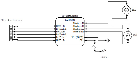
We used the L298N Half-bridge module provided by ME210 in order to drive our motor circuit. Each channel was designed to source or sink up to 2A of current. We utilized the module in a standard, unmodified condition. We included a motor kill switch on the 12V rail supplying the board in order to allow us to test the robot without having it run away from us when we didn’t want it to.
During testing we found a glitch in our circuit design. Because our Arduino and H-bridge driver were connected to the same 12V rail, the Arduino became susceptible to voltage drops generated by the motor during certain conditions. Because our chips were not designed to allow for dynamic breaking of the motors, we chose to pulse the motors in reverse in order to stop the robot. This however seemed to cause tremendous voltage drops across our 12V rail resulting in the Arduino unit shutting down and restarting. |
Tape Sensors
We built six tape modules for our robot. The circuits for each were constructed identically as shown below:
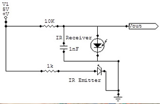
Our tape modules were relatively simple circuits. We did some testing with the resistor values in order to make sure that the values that we were reading could extend across nearly the entire range of the A/DC convertor of the Arduino. Initially this was important because we were going to use the analog value of the tape sensors in order to vary our motor speeds for a real-time motor correction algorithm. Unfortunately, we abandoned our tape sensors in order to focus on developing a more robust robot with a lean towards beacon sensing. During testing we were able to read a value of 40 off of a reflective surface and up to 950 on the non-reflective tape. Giving us nearly 90% of the effective A/DC range.
Power Circuit
For our power circuit, we chose to cascade our voltage regulators in order to minimize complexity and allow for a single ‘kill’ switch. Two 7.2V battery packs connected in series provided just over 14V going into the 12V regulator. The regulator supplied 12V power to our motor H-bridge and Arduino unit, modeled here as ‘12V Load’. The regulator also supplied two 5V regulators connected in parallel to increase the amount of current that we were able to source at 5V. We felt this was necessary because we felt that a single regulator was overheating when trying to supply all of our 5V power demands such as the tape sensors, beacon sensors, and servos.
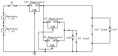
Capacitors were placed on the rail to stabilize the output voltages of the system.
Bump SensorsOur robot also included two bump sensors. The circuit for both sensors was conceptually identical as shown below:
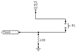
We incorporated a 10M pull-down resistor on the circuit in order to ensure that our reference for the Vout to the Arduino was not floating and was actually pulled below the digital low threshold of the Arduino.
|
